Page 65 - Fan Coil Unit
P. 65

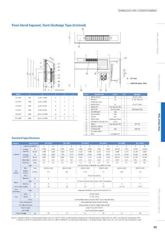
Floor-Stand Exposed, Slant Discharge Type (Inclined)

                                                            15
                                                                                                                   Ceiling Cassette Type


                                                         14


                                                                                           13
                              1
                                           3
                              2            4
                                           5                                              Power
                                                                                          Cord
                                                                                          1.5 M
                                                               12    11                   External
                                           7                                              Cord
                                                                                          1 M
                                           8                                                   Air Flow
                                           10
                                                                                               Cold/Hot Water Flow  Concealed Type
                                         LEVELING BOLT     16             9  6
             MODEL    A        B         C     D      E       Part No  DESCRIPTION  MAT’L  Q’TY   REMARK
            SFC-20FT  940    p120 x 4=480  4   1      1        1   WATER OUTLET     BS    1      PF 3/4" (20 A)
                                                               2   AIR VENT         BS    1     PT 1/8" (Manual)
            SFC-30FT  1060   p120 x 5=600  5   1      1        3   INNER SIDE CASE        2
                                                               4   WATER INLET      GI    1      PF 3/4" (20 A)
            SFC-40FT  1180   p120 x 6=720  6   1      2        5   DRAIN PAN    Heat-Resistant ABS  1
            SFC-60FT  1420   p120 x 8=960  8   1      2        6   AIR FILTER    Vinyl Chloride  1  Submerged Type
                                                               7   FAN IMPELLER    ABS    E
            SFC-80FT  1660  p120 x 10=1200  10  2     3        8   FAN HOUSING     ABS    E
                                                               9   MOTOR           ASS’Y  D
            SFC-120FT  1900  p120 x 12=1440  12  2    4
                                                               10  DRAIN HOSE   Soft Polyvinyl Chloride  1
                                                               11  HEATING & COOLING COIL  CU-AL  1                 Floor-Stand Type
                                                               12  GRILLE       Heat-Resistant ABS  C  120*120
                                                               13  CONTROL SWITCH         1
                                                               14  ACCESS DOOR     ABS    2       120*200
                                                               15  EXTERNAL PANEL         1
                                                               16  BASE          Composite PP  2
          Standard Specifications

          Category    Specifications  SFC-20FT  SFC-30FT    SFC-40FT     SFC-60FT     SFC-80FT     SFC-120FT
                  Capacity Conditions  A  B   A     B      A     B      A      B     A      B     A      B
                  Cooling   W  2,790  2,120  3,700  2,810  5,360  4,050  7,220  5,490  10,440  7,870  13,610  10,260
                 Capacity  Kcal/h  2,400  1,820  3,180  2,420  4,610  3,480  6,210  4,720  8,980  6,770  11,700  8,820
           Capacity  Heating   W  5,640  3,460  7,780  4,770  10,990  6,710  14,330  8,760  21,240  12,950  23,640  14,340
                 Capacity  Kcal/h  4,850  2,980  6,690  4,100  9,450  5,770  12,320  7,530  18,270  11,140  20,330  12,330
                 Flow Rate  ℓ/min  8.1   6.0   10.7   8.0   15.4   11.5   20.8   15.7   30.0   22.4   39.1   29.3
                 Head Loss  mAq  0.7   0.4   1.6    0.9   4.4    2.4    3.5   2.0    9.5   5.3    16.8   9.4        Stand Type
                      Type                               Double Suction Multi-Blade Type (SIROCCO FAN)
                   SIZE  mm      Ø145 X L165  Ø145 X L200  Ø145 X L165   Ø145 X L200  Ø145 X L200  Ø145 X L200
            Fan    Airflow   m /min  5.7         8.5         11.3          17           22.6          34
                         3
           Blower  Volume
                  Drive                                          Direct Drive Motor
                 Quantity  EA       1            1            2            2             3            4
                      Type                               AC Semi-Enclosed Type (6 poles, Class B insulation)
           Motor
                 Quantity  EA       1            1            1            1             2            2
           Power Consumption  W    30            40           50           70          40 + 70       70 X 2
            Heat
          Exchanger   Type                               Integrated Multi-Pass Cross Finned Tube (Slit Fin)
                  Inlet   A                                       PF 3/4" (20 A)
            Pipe  Outlet  A                                       PF 3/4" (20 A)
                     Drain                             Soft Vinyl Hose (Inner Diameter Ø14, Outer Diameter Ø18)
               External Material                           Galvanized Steel Sheet, Powder Coating                   Facility Cultivation Type
               Air Volume Control                         Strong, Medium, Weak 3-Stage Rotary Switch
                Power Supply                                   Single Phase 220 V 60 HZ
                 AIR FILTER                                   Vinyl Chloride (Submerged)
            Product Weight  Kg     24            27           31           36           41            49
          (Note) 1. Capacity Condition A: Cooling Capacity: When indoor air is DB 27°C, WB 21°C, and inlet water temperature is 5°C Heating Capacity: When indoor air is 18°C, and inlet water temperature is 80°C
             2. Capacity Condition B: Cooling Capacity: When indoor air is DB 27°C, WB 19.5°C, and inlet water temperature is 7°C Heating Capacity: When indoor air is 21°C, and inlet water temperature is 60°C

                                                                                                                65
   60   61   62   63   64   65   66   67   68   69   70