
Page 35 - Energy Recovery Ventilation
P. 35
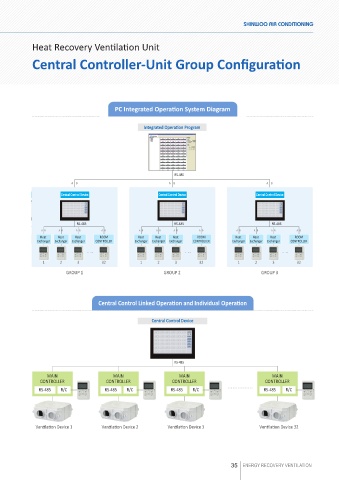
Heat Recovery Ventilation Unit

            Central Controller-Unit Group Configuration


                                         PC Integrated Operation System Diagram


                                                    Integrated Opera�on Program

                                                    Integrated Opera�on Program


                                                              RS-485
                          A B                               A B                                A B
                                                              RS-485
                      Central Control Device             Central Control Device            Central Control Device
                          A B                                A B                               A B
                       Central Control Device            Central Control Device            Central Control Device

                            RS-485                            RS-485                            RS-485
                A B   A B   A B      A B          A B   A B   A B      A B          A B   A B   A B      A B
               Heat   Heat   Heat   ROOM         Heat   Heat   Heat   ROOM          Heat   Heat   Heat   ROOM
                            RS-485
                                                              RS-485
                                                                                                 RS-485
              Exchanger  Exchanger  Exchanger  CONTROLLER  Exchanger  Exchanger  Exchanger  CONTROLLER  Exchanger  Exchanger  Exchanger  CONTROLLER
                A B   A B   A B      A B          A B   A B   A B      A B          A B   A B   A B      A B
               Heat   Heat   Heat   ROOM          Heat   Heat   Heat   ROOM         Heat   Heat   Heat   ROOM
              Exchanger  Exchanger  Exchanger  CONTROLLER  Exchanger  Exchanger  Exchanger  CONTROLLER  Exchanger  Exchanger  Exchanger  CONTROLLER
                1     2     3        32           1     2     3        32            1     2     3       32
                        GROUP 1                            GROUP 2                           GROUP 3
                1     2     3        32           1      2     3       32            1     2     3       32
                        GROUP 1                            GROUP 2                           GROUP 3

                                    Central Control Linked Operation and Individual Operation
                                                      Central Control Device


                                                      Central Control Device


                                                              RS-485

                 MAIN                    MAIN                 RS-485                            MAIN
                                                                MAIN
               CONTROLLER             CONTROLLER             CONTROLLER                       CONTROLLER
               RS-485     R/C         RS-485     R/C         RS-485     R/C                   RS-485     R/C
                  MAIN
                                                                MAIN
                                                                                                 MAIN
                                         MAIN
               CONTROLLER             CONTROLLER             CONTROLLER                       CONTROLLER
               RS-485  R/C            RS-485  R/C            RS-485  R/C                      RS-485  R/C
             Ven�la�on Device 1      Ven�la�on Device 2     Ven�la�on Device 3              Ven�la�on Device 32


              Ven�la�on Device 1     Ven�la�on Device 2     Ven�la�on Device 3              Ven�la�on Device 32


                                                                                  35 ENERGY RECOVERY VENTILATION