
Page 75 - Fan Coil Unit
P. 75
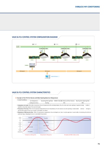
VALVE & FCU CONTROL SYSTEM CONFIGURATION DIAGRAM


                                        AC 220 V                AC 220 V                AC 220 V
                    FCS / FHS
                    FCR / FHR
                                              Combina�on Valve        Combina�on Valve         Combina�on Valve


                                    TVS-05        FCU        TVS-05        FCU       TVS-05        FCU


                             GATEWAY


                       IBS Network                  IBS Network                         IBS Network


                                                           VALVE & FCU System


               VALVE & FCU CONTROL SYSTEM CHARACTERISTICS


                   ▶ Example of the FCU Air Volume and Valve Opening Based on Temperature
                      • Control Conditions:
                                   Set Temperature  Operating/Driving Mode  RANKUP (Variable Rate by Airflow Volume)  Heating Valve Opening Rate
                                   28 degrees Celsius  Heating           20%                  80%
                    •  Temperature Increase: When the temperature rises and approaches the set temperature, the air volume and valve opening is lowered (strong ⇨ medium ⇨
                     weak) to reduce the supply of hot and cold water.
                    •  Temperature Decrease: When the temperature drops below the set temperature, the air volume and valve opening is raised (weak ⇨ medium ⇨ strong) to
                     increase the supply of heat source water (cold water, hot water).
                    •  Temperature Maintenance Zone:  When the temperature approaches the set temperature, the air volume operates in weak mode, maintaining the minimum
                     valve opening or stopping to ensure a consistent temperature.

                       30        Stop (0%)
                       29                          Stop (0%)
                       28
                       27        Weak (48%)        Weak (48%)
                       26
                       25                         Medium (64%)
                       24       Medium (64%)
                       23
                       22                          Strong (80%)
                     Temperature  Strong (80%)
                             Temperature Rising Zone  Temperature Falling Zone  Temperature Maintenance Zone


                                                                                                                75