
Page 91 - Fan Coil Unit
P. 91
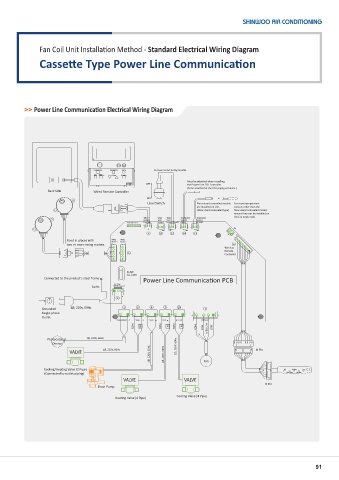
Fan Coil Unit Installation Method - Standard Electrical Wiring Diagram
               Cassette Type Power Line Communication


          >> Power Line Communication Electrical Wiring Diagram


                                  Func on Selec on  Timer Opera on  Filter Set  No Power Contact (Ceiling Casse e)
                                  Fan  Airflow
                                  Speed  Direc on  Low/High  Sleep Mode
                                                                   Must be a ached when installing
                                                    OFF            the Power Line FCU Controller.

                                                                   (To be a ached at the FCU piping entrance.)
                  Back Side       Wired Remote Controller
                                                     ON                       or
                                                     Level Switch     Floor-stand concealed models   For room temperature
                                                                      are installed on-site.   sensors other than the
                                                                      (Floor-stand concealed type)  floor-stand concealed model,
                                                                                   ensure they can be installed on
                                                                                   the fan intake side.
                                                   Wired   Water   Water   Temperature   Temperature
                                                   Remote   Level   Level   Sensor 2   Sensor 1
                                              Ethernet Port1  Controller  Sensor 2  Sensor 1 (Level)  (PIPE)  (ROOM)
                                                     9   13  12  14  11
                         Used in places with   Swing   Swing
                                           Motor 2
                                        Motor 1
                         two or more swing motors.                                 6
                                                                                Wireless
                                                                                Remote
                                              5                                 Controller
                                              FUSE
                                              3A, 240V
                 Connected to the product's steel frame  Power Line Communica on PCB
                                         AC 220V
                                 Earth   INPUT (Power)
                                          8
                Grounded   1Ø, 220v, 60Hz   2    3    4    7   10        1
                Single-phase
                Outlet
                                          Photocatalyst  Valve  Drain  Heat  Cool  FAN Motor
                                                COM  NO   COM  NO  COM  NO  COM  HIGH  MEDIUM  LOW
                                                                       x
                  Photocatalyst   1Ø, 220V, 60Hz
                   Device                                      1Ø, 220V, 60Hz
                                                      1Ø, 220V, 60Hz  1Ø, 220V, 60Hz  Fan
                         VALVE       1Ø, 220V, 60Hz                                        8 Pin

                Cooling/Hea ng Valve (2 Pipe)                                                x          Cooling  Fan
                 (Connected to outlet piping)                                                         Opera on  Hea ng
                                            VALVE                 VALVE
                                                                                              9 Pin
                                   Drain Pump
                                         Hea ng Valve (4 Pipe)  Cooling Valve (4 Pipe)


                                                                                                                91